Object moved
WEBObject moved to here.
WEBObject moved to here.
WEBThe sealing performance of the gear not only affects its service life but also relates to the overall maintenance frequency of the whole ball mill system. Material of Girth Gears. The hardness of the ball mill girth gear should be above HB300, and the hardness of the ball mill pinions should be above HRC45. If the hardness of the gear is not up ...
WEBThe cost of edge drive is low, but the pinion needs to be replaced every 25 years Edge drive is mainly used in coal mills and mills with small power The girth gear(big ring gear) and pinion are the key of the edge transmission device Their reliable operation is directly related to the stable production of the mill In order to ensure their Gears ...
WEBMaruti Enterprise Offering Kiln Girth Gear (Ball Mill Girth Gear), For Machinery at Rs in Ahmedabad, Gujarat. Also find Fertilizer Plants price list | ID:
WEBBall Mill Girth Gear Radial From Uganda SOF Mining machine. Cr4 thread ball mill girth gear and pinion alignment aug 28 2011 re ball mill girth gear and pinion alignment 207 am pinion alighnment is done by coating the pinion with a lead based grease after rotating the drum the grease marks will show the contact area the pinion should .
WEBApr 30, 2023 · Consult the gear manufacturer's specifiions to determine the required amount of backlash. Step 3: Adjust the gears – To increase the backlash, move the gears further apart. This can be done by loosening the mounting bolts and shifting the gears to the desired position. To decrease the backlash, move the gears closer together.
WEBBALL MILL ALIGNMENT. Ball mills are rotary equipment with relatively high speed of operation commonly used at industry. In fact, due to this higher speed of rotation all the components: pinions, gears, main and auxiliary drives has to be set in a very precise way. Mutual, correct positioning of such elements guarantees their durable and long ...
WEBJan 16, 2019 · How do you measure the root clearance between a girth gear and a pinion of a grinding ball mill and what is the recommended root clearance. This ball mill uses helical gears( 284 teeth girth gear with a 24 teeth pinion).
WEBTel: . Send your inquiry directly to us ( 0 / 3000) High quality Ball Mill Girth Gear And Rod Mill Girth Gear And AG Mill Girth Gear And Sag Mill Girth Gear from China, China's leading kiln girth gear product, with strict quality control ball mill girth gear factories, producing high quality 100 tpd kiln girth gear products.
WEBSep 1, 2009 · The tooth fillet design is based on completely defined involute flank parameters. The initial fillet profile is a trajectory of the mating gear tooth tip in the tight (zero backlash) mesh. For practical purpose, this trajectory is defined at the minimum center distance (including both of the gear's runout), maximum tooth thickness, and ...
Screw Gears Cylindrical Worm Gear Pair Tooth Thickness; Chordal Tooth Thickness Measurement Span Measurement of Teeth Measurement Over Rollers Gear Backlash; Definition of Backlash Backlash Relationship Tooth Thickness and Backlash Gear Train and Backlash Methods of Reducing Backlash .
WEBApr 10, 2024 · In common usage, the term can refer to the spaces themselves or the loss of motion resulting from the spaces when a gear direction is reversed. In other words, backlash can be defined as the excess wideness of a space between teeth of one gear compared to the thickness of the tooth of its mating gear. Both the resulting gap and .
WEBLarger torques of up to 4,000 kNm are serviced by a combination of our XP series industrial planetary gear units and the X series industrial bevelhelical gear units. Large girth gears are installed around the cylinder to rotate the horizontal ball mill cylinders. A pinion connects these directly to the industrial gear unit.
WEBA dial gauge E is placed at the midpoint of girth gear tooth width. The micrometer pointer is to be vertically measured to measure the radial runout of girth gear; a dial gauge A is placed on the end face of the girth gear to measure the end face runout of the girth gear; two dial gauges B and C are respectively placed at the shoulder of the ball mill trunnion .
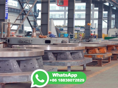
WEBTechnical Parameter: Usage: industry Model: Φ Material: cast steel Modulus: 16 Number of teeth: 154 Tooth height: 50mm Tooth width: 250mm Weight: 3500kg Tooth surface hardness: hard surface Tooth line shape: spur gears QTY: 1set Detailed Information: Today we delivery one set girth gear for ball mill to South .
WEBMechanical. Gear tooth (train) thickness backlash calculator formula step by step calculation to find the motion loss due to gaps between the gear teeths or train in a mechanical system. b t = t i t a. Ideal tooth thickness in mm actual tooth thickness in mm are key elements of this calculation.
WEBApr 19, 2020 · Girth Gear Pinion Infrared basics. The infrared alignment technique should only be applied to mill gear pinions not kiln or dryer gears. Kiln and drier systems typically run slow and do not develop sufficient temperatures from the mesh forces and can be significantly affected by heat transfer from the kiln or drum.
WEBWe have a strong production capability to manufacture ball mill accessories according to the PDF or CAD drawings provided by customers. If you have any needs, please contact us! Ball mill cylinder, ball mill end cover, ball mill grinding media, ball mill lining plate, and ball mill girth gear are five mustknow ball mill spare parts.
WEBMar 4, 2023 · The first step in girth gear alignment is preparation. The equipment must be shut down and deenergized, and safety protocols should be followed. Once safety measures are in place, the equipment should be cleaned, and any debris or dirt removed. The second step is measuring the alignment of the girth gear and pinion.
WEBMar 8, 2021 · Dialing It In. Once fully seated, install and tighten down the carrier pads. Always install and tighten the right side first. With the carrier assembly installed, attach your dial indior with the plunger at a 90degree angle from the face of the ring gear teeth. Gently rock the carrier back and forth to measure your backlash.
WEBOct 19, 2016 · Ball Mill Sole Plate. This crown should be between .002″ and . 003″, per foot of length of sole plate. For example, if the sole plate is about 8′ long, the crown should be between .016″ and .024″. Ball Mill Sole Plate. After all shimming is completed, the sole plate and bases should be grouted in position.
WEBDesign and calculation of a ball screw. Load analysis, life calculation and tolerances. Check for tension/pressure, buckling and critical speed
© DZCrusher - كل الحقوق محفوظة
خصوصية · شروط · خريطة الموقع
